In my archaeological exploration of old computer files, I came across another simple but exciting Amiga Basic program I programmed in 1989. It is named “Foglie”, the Italian name for leaves. It was an attempt to explore some ideas of functional plant morphology modelling. The stimulus comes after the reading of the paper by Karl J. Niklas on issue 213 of Le Science (the Italian edition of the Scientific American magazine [1]). The article titled “Computer-simulated plant evolution” described the modelling of plants to study their interaction with the environment. It was a fascinating paper; still, simple and primitive graphics caught my imagination. Nowadays, the field of digital morphology has come to an age (just to mention one, Avatar), and we can have an idea of this progress in the level of realism in movies, video games, and TV programs. However, the organism’s form and shape have always caught my curiosity and interest. The structure of leaf nervation was an intriguing pattern related to my acquaintance with the fascinating fractals objects, another recurrent topic in the pages of scientific magazines of the period.
At that time, I did also my first upgrade from the “mythical” Commodore VIC 20 to the then rising stars MSX computers (MSX was a standardized home computer architecture popular in the ’80. Different companies invested money in this new system, and my lovely parents gave me as a gift MSX Philips VG-8010). The superb graphics capability of the MSX basics (an extended version of the Microsoft Basic) compared to the Commodore systems allowed me to dive quickly into programming computer graphics. Among the various projects, I did program a two-dimensional version of the Niklas algorithm and the first version of the program named Foglie.
I discovered later that the theoretical morphology of plants and other organisms moves in two directions. The so-called symbolic language and the functional approach. The first one was invented by Aristid Lindenmayer and named L-systems in his honour [1]. This approach owes much to self-similarity and the programming approach introduced in the 70 with the programming languages PILOT and LOGO [2]. This approach describes the structure of the plant in term of self-recurrent strings that encapsulates a few simple repetitive commands. On the contrary, the functional approach tries to describe the organism’s morphology with mathematical functions. A typical example is the shape of the seashell (I will cover this argument in detail in another blog), which can be approximated, for example, by rescaling and translating the shell opening along an helico-spiral. My original idea to model the shape of leaves in two dimensions was based on a functional approach. Unfortunately, I didn’t progress much in this direction since my early programming projects were of a young amateur with little experience in scientific research. Still, I got some initial promising results. Therefore, I revisited the idea a few years after (1993) when, owning an Amiga 500 (see my previous blog here), I rewrote the program in Amiga Basic, adding other ideas for making the model more realistic.
The program generates a leaf shape in two dimensions given a set of parameters. In particular, it requires the number of secondary veins detaching from the central one, the angle of detaching, the number of segments in the secondary veins and the progressive curvature of the segments going form the attachment to the periphery. Once the simplified skeleton was generated the terminal points of the secondary nerves are connected with functions of different convexity to simulate the border of the leaf lamina. The program is very simplistic but the shape resembles quite impressively the shapes of different type of leaves.
I have run the program using FS-UEA Amiga emulator on a MacBook laptop, and, in Figure 1, some results are reported. The copy of the program is also provided in the Appendix if there is some interest to explore the code.
Since my isolated and primitive attempts to reproduce the shape of leave, there has been a considerable progress in this area also bursted by application in computer graphics and movie industry. The mathematician Brian Hayes has recently published in his wonderful blog site (bit-player.org), an very interesting account of the recent progress in this area [4] with very useful references.
Still I am really very pleased of the results of my algorithm an probably I will provide an updated version, so stay tunes on my blog!


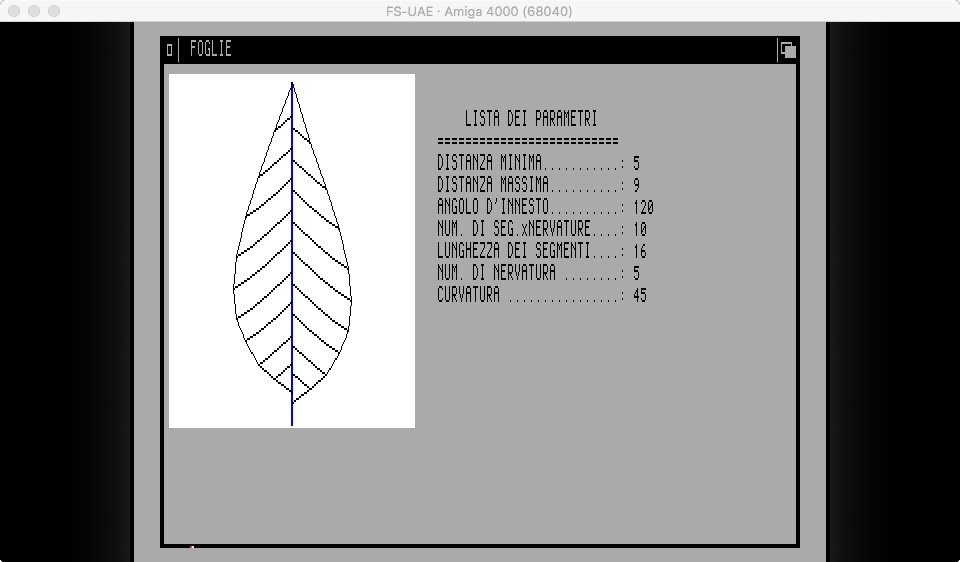
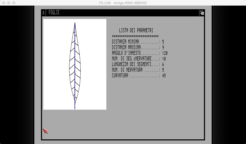

Figure 1: Example of output by the program Foglie.
REFERENCES
- K.J Niklas. Computer-simulated plant evolution. Scientific American. 254(3), 78-86, March 1986.
- Prusinkiewicz P, Lindenmayer A. The Algorithmic Beauty of Plants. New York: Springer-Verlag; 1996. A free preprint is also available here.
- Abelson H, DiSessa A.A. Turtle Geometry: The Computer as a Medium for Exploring Mathematics (MIT Press Series in Artificial Intelligence); 1986.
- Brian Hayes. More Questions About Trees. http://bit-player.org/2020/more-questions-about-trees (last check on Nov. 5th 2020).
APPENDIX
Program in Amiga Basic used to generate the shapes in Figure 1.
'********************************************************************
' FOGLIE
'
' VERSIONE AMIGA 4/1/1989
' (adattato da una versione scritta per MSX nel 1986)
' Revisione e correzione: 11/7/1993
'
' DESCRIZIONE
' Il programma serve a generare delle configurazioni di nervature
' fogliari variando alcuni parametri geometrici.
'
' LISTA DEI PARAMETRI
'
' a=distanza minore tra due nervature sulla nervatura centrale.
' b=distanza maggiore tra due nervature sulla nervatura centrale.
' g=angolo d'innesto (angolo tra la nervatura centrale e quelle
' laterali.
' n=numero di nervature che partono dalla nervatura centrale.
' l=lunghezza segmenti che costituiscono le nervature secondarie.
' c=numero di segmenti di ogni nervatura secondaria.
' fat=inverso del coefficiente per la curvatura delle nervature
' secondarie.
'
' (c) D. Roccatano 1986-1993
'********************************************************************
SCREEN 1,640,256,4,2
WINDOW 2,"FOGLIE",,14,1

RANDOMIZE TIMER

DIM nerv(2,1,200)
pi=ATN(1)*4

' Inizializazione parametri

a=5
b=9
c=5
g=120
n=10
l=80/c
fat=120

'
' PRINT PARAMETERS
'

LOCATE 3,40:PRINT " LISTA DEI PARAMETRI "
LOCATE 4,40:PRINT "=========================="
LOCATE 5,40:PRINT "DISTANZA MINIMA...........:";a
LOCATE 6,40:PRINT "DISTANZA MASSIMA..........:";b
LOCATE 7,40:PRINT "ANGOLO D'INNESTO..........:";g
LOCATE 8,40:PRINT "NUM. DI SEG.xNERVATURE....:";n
LOCATE 9,40:PRINT "LUNGHEZZA DEI SEGMENTI....:";l
LOCATE 10,40:PRINT "NUM. DI NERVATURE ........:";c
LOCATE 11,40:PRINT "CURVATURA ................:";fat

' Definizione della funzione che descrive il profilo della lamina
' fogliare

'DEF FNlun(nseg)=l
DEF FNlun(nseg)=l*SIN(pi*(nseg)/n)
'DEF FNlun(nseg)=l*((n-seg)/n)
'DEF FNlun(nseg)=l*SIN(pi*(nseg)/n)*SIN(pi*(nseg)/n)

'
' Calcola i punti di innesto sulla nervatura centrale delle
' nervature secondarie
'

gg=0
x=0
y=0

ciclo1:
FOR t=0 TO 2*n STEP 2
k=INT(RND*3)
h=INT(RND*2)
y=y+b+k
nerv(0,1,t)=y
nerv(0,0,t)=x
y=y+a+h
nerv(0,1,t+1)=y
nerv(0,0,t+1)=x
NEXT t

'
' Calcola il nodo del primo segmento delle nervature secondarie
'
nseg =0

ciclo2:
FOR t=0 TO 2*(n-1) STEP 2
x1=nerv(0,0,t)
y1=nerv(0,1,t)
x2=x1+FNlun(nseg)*SIN((g*pi)/180)
y2= FNlun(nseg)*COS((g*pi)/180)
yk=y2+y1
nerv(1,0,t)=x2
nerv(1,1,t)=yk
nerv(1,0,t+1)=-x2
y3=nerv(0,1,t+1)
yh=y2+y3
nerv(1,1,t+1)=yh
NEXT t
IF c=1 GOTO graf
'
' Calcola i nodi degli altri segmenti delle nervature secondarie
'
ss=2*n
m=2
rr=2*n
nseg=0

ciclo3:
FOR tt=1 TO c-1
FOR t=ss TO 2*(rr-1) STEP 2
x1=nerv(1,0,t-2*n)
y1=nerv(1,1,t-2*n)
y2=nerv(1,1,t-2*n+1)
FOR z=2 TO m
gg=gg+g/fat
IF (g-gg) =< 0 THEN gg=gg+g/z:GOTO sub2
NEXT z
sub2:
q=((g-gg)*pi)/180
x2=x1+FNlun(nseg)*SIN(q)
y3= FNlun(nseg)*COS(q)
nerv(1,0,t)=x2
nerv(1,1,t)=y1+y3
nerv(1,0,t+1)=-x2
nerv(1,1,t+1)=y2+y3
gg=0
nseg=nseg+1
NEXT t
gg=0
nseg=0
ss=2*rr
rr=rr+n
m=m+1
NEXT tt

graf:
'
' Disegna rettangolo di contorno e nervatura centrale
'
LINE(5,5)-(250,181),2,bf
LINE(127,180)-(nerv(0,0,2*n+1)+128,180-nerv(0,1,2*n+1)),4,b
'
' Disegna primo segmento delle nervature secondarie
'
FOR tt=0 TO 2*(n-1)
LINE(nerv(0,0,tt)+128,180-nerv( 0,1,tt))-(nerv(1,0,tt)+128,180-nerv(1,1,tt))
LINE(nerv(0,0,tt+1)+128,180-nerv( 0,1,tt+1))-(nerv(1,0,tt+1)+128,180-nerv(1,1,tt+1))
NEXT tt
'
' Disegna altri segmenti delle nervature secondarie
'
sub1:
ss=2*n
rr=2*n
FOR t=1 TO c-1
FOR tt=ss TO 2*(rr-1) STEP 2
LINE(nerv(1,0,tt-2*n)+128,180-nerv(1,1,tt-2*n))-(nerv(1,0,tt)+128,180-nerv(1,1,tt)),1
LINE(nerv(1,0,tt-2*n+1)+128,180-nerv(1,1,tt-2*n+1))-(nerv(1,0,tt+1)+128,180-nerv(1,1,tt+1)),1
NEXT tt
ss=2*rr
rr=rr+n
NEXT t
'
' Disegna profilo della lamina
'
rr=rr-n
ss=2*(rr-n)

FOR tt=ss TO 2*(rr-2) STEP 2
LINE(nerv(1,0,tt)+128,180-nerv(1,1,tt))-(nerv(1,0,tt+2)+128,180-nerv(1,1,tt+2)),1
LINE(nerv(1,0,tt+1)+128,180-nerv(1,1,tt+1))-(nerv(1,0,tt+3)+128,180-nerv(1,1,tt+3)),1
NEXT tt

tt=tt-2
LINE(nerv(1,0,tt+2)+128,180-nerv(1,1,tt+2))-(nerv(0,0,2*n+1)+128,180-nerv(0,1,2*n+1)),1
LINE(nerv(1,0,tt+3)+128,180-nerv(1,1,tt+3))-(nerv(0,0,2*n+1)+128,180-nerv(0,1,2*n+1)),1

GOTO sub1

